While fitting hardware limit switches to the CNC I accidently touched a stepper motor connector with a screwdriver and heard a pop. I thought nothing of it at the time, however I soon started to notice the Z axis was loosing steps, causing it to continually drop during a program. The Z height would be fine at the start of a program but would gradually drop, causing larger and larger depths of cut. I created a G-Code program that only moves the Z axis up and down its full length to confirm the problem. After only a few full movements of the Z axis the drop in height was clear to see, even by eye.
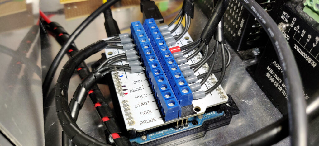
The issue of using a Arduino connected to the controller via a parallel cable as seen in part one was also getting annoying. So, after doing some feasibility research I decided to create my own CNC controller based upon an Arduino GRBL and some pre-made stepper controllers.
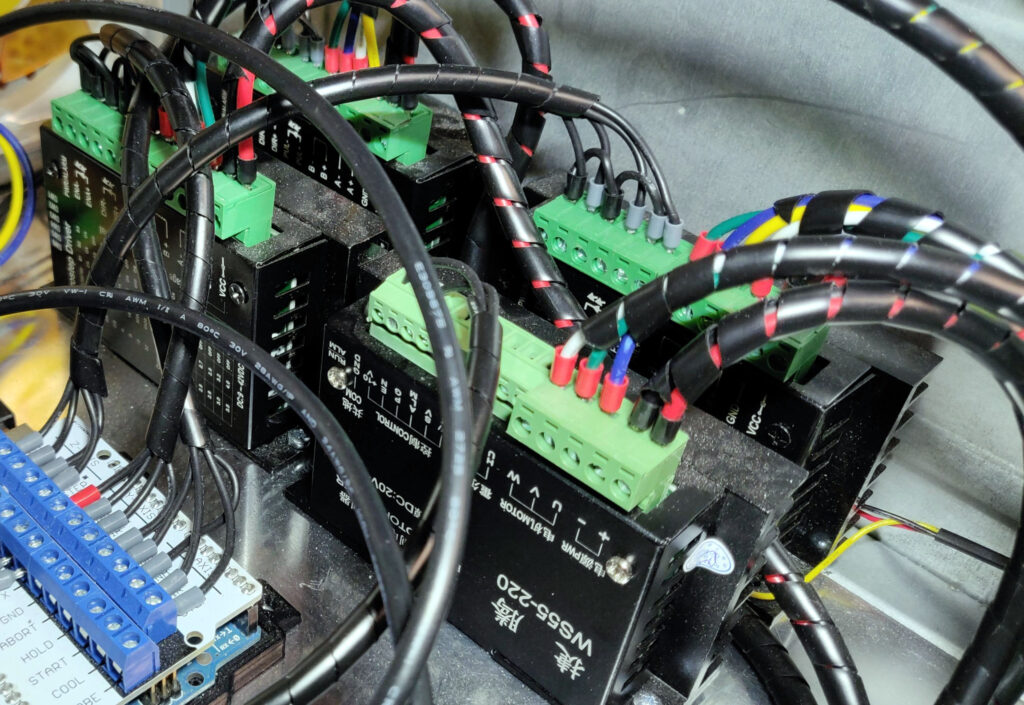
STEPPER CONTROLLERS
Because this was my first time creating a CNC controller I decided to go with what seemed to be the most popular choice for stepper controller, the TB6600. The reason being that I knew they where compatible with the Arduino running GRBL, eliminating a potential problem if troubleshooting is required. The controller wires up to the Arduino using only three wires, 1.Direction 2.Pulse 3.Ground.

The stepper motor controllers come in their own enclosure, complete with heatsink too.
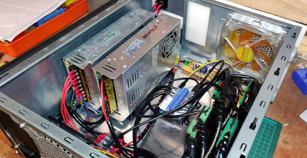
POWER
To power the stepper motor controllers a supply is needed, powerful enough for the rated motor current. The voltage of the supply does not really matter as the stepper motor driver controls and limits the motor current, explained here: Misconceptions about Stepper Motors Explained.
The supplier of the machine and none of the accompanying paperwork mention the stepper motor current, however after some Googling I assume they are 2A motors, this seems to be the most common size motor for this machine size. Therefore a supply capable of 6A would be needed (2A x 3) for the X,Y & Z motors.
I decided to go with a 36V 8A power supply, this’ll power both the stepper motors and the Arduino controller (Via a 5V voltage regulator).
LIMIT SWITCHES
The limit switches on the CNC both tell the controller where the spindle is and stops the gantry from crashing into itself. These switches are located at the ends of travel for each axis and consist of a lever with roller.
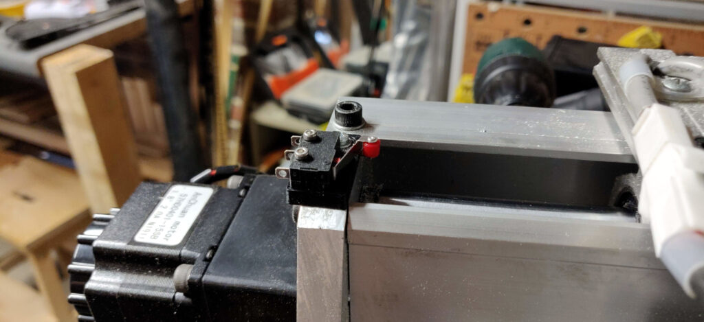
Wiring of the switches to the Arduino is explained in detail on the GRBL wiki. Below is a drawing of what I did for each axis to connect both limit switches, one for each end of travel.

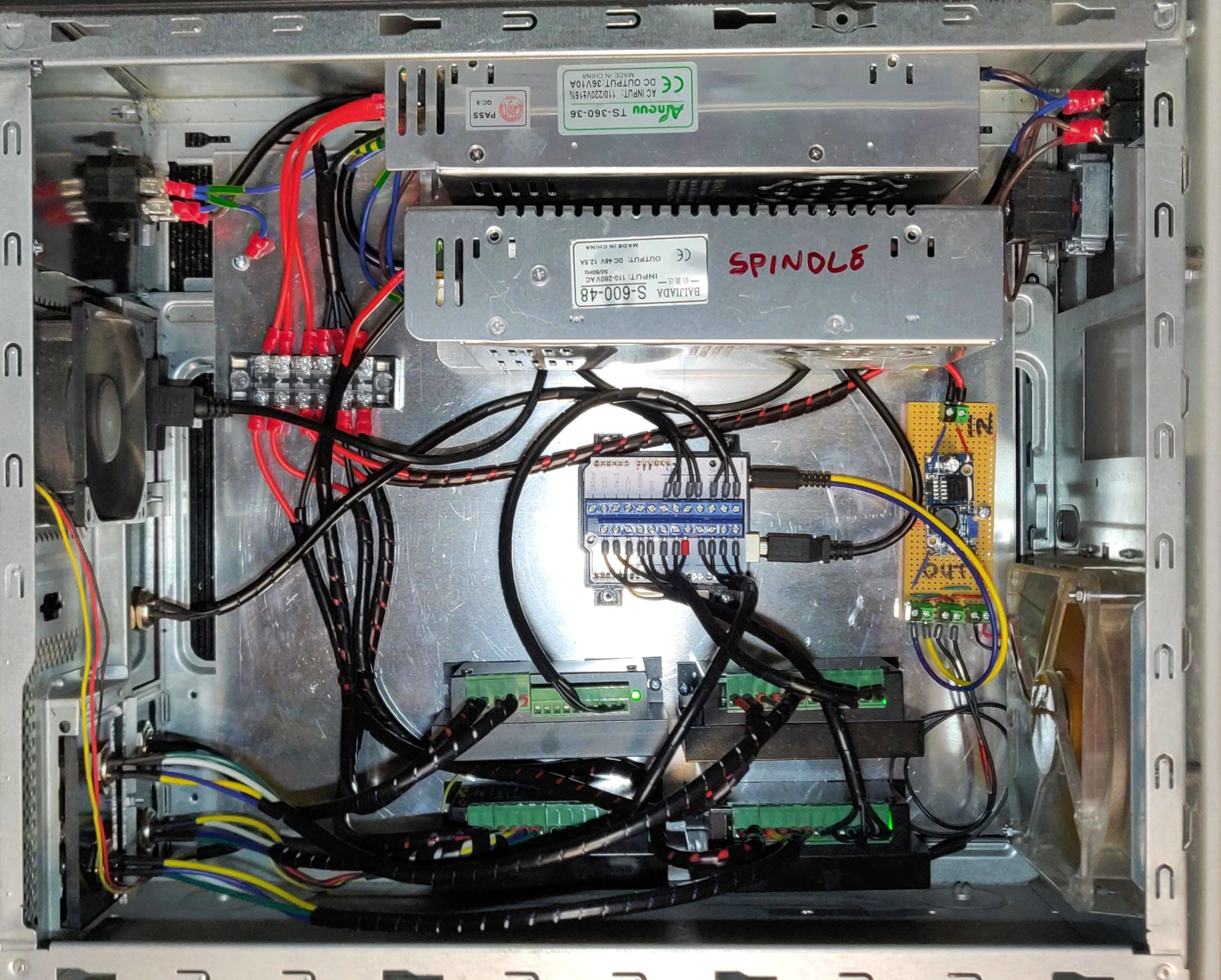
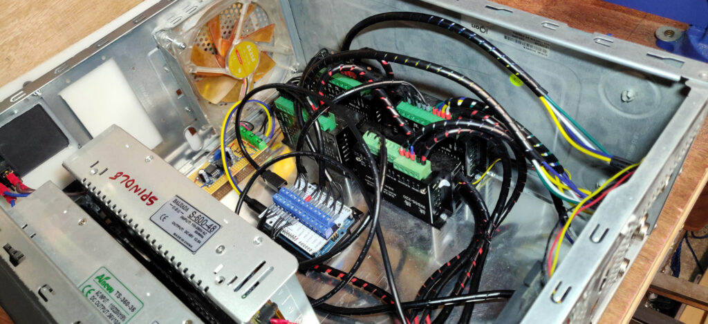
CASE
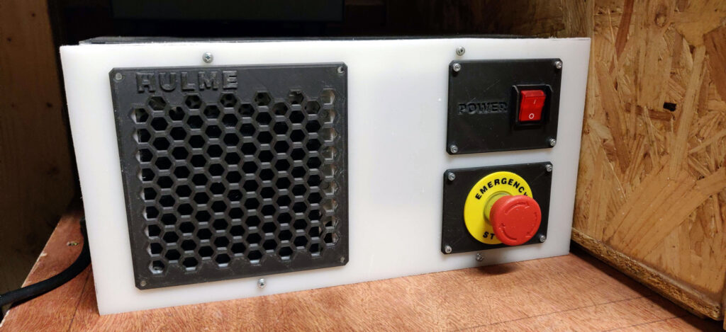
To house all of these components, protecting them from debris and me from electrical current, I used an old PC case. This was the perfect size and already built. But to complement the build I designed and installed some panels for the front of the case. The first is an emergency stop, connected to the main power supply. This’ll disconnect the power supply, stopping the motors and spindle from causing anymore damage.
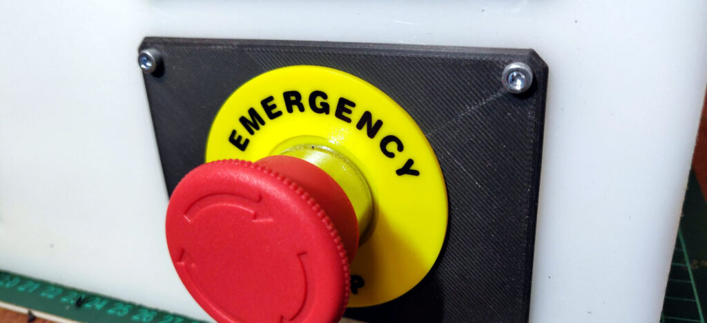
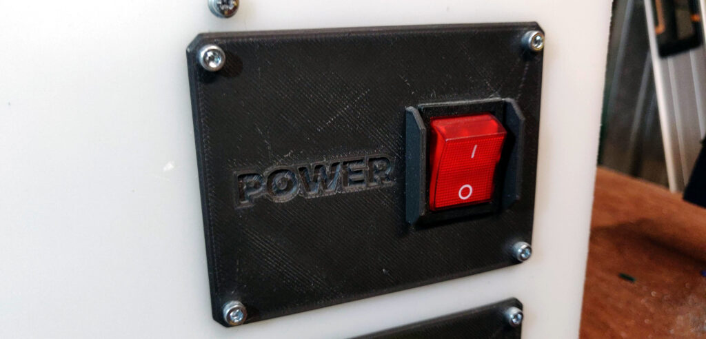
The next panel was a main power switch, wired inline after the emergency stop. The switch is self illuminating, indicating at a quick glance that the power is on. The 3D printed side guards stop and accidental power loss due to bumping into the switch.
ASSEMBLY
RESULTS
The initial motivation for creating a new controller was due to a damaged stepper motor controller on the z axis, causing step losses. After installing the new controller and running the same test as before, moving the z axis up and down I could instantly see a noticeable difference. No more step losses resulting in the axis dropping. The other motivation for creating a new controller was to stop using the janky wiring of a Arduino connected to a parallel cable. The new case is fully enclosed and all the cables safely behind panels.