
Pass a current through a coil of wire and you’ll create a magnetic field. A solenoid engine uses this magnetic field to create mechanical movement, its an neat way of creating mechanical work and it can create some great looking machines, especially as a desktop trinket.
The design of a solenoid engine it not too dissimilar to an internal combustion engine design, there’s a piston, rod, crankshaft and flywheel. The difference being that an ICE uses the explosive force of igniting fuel to create movement and a solenoid engine uses magnetic fields generated by the coil of wire.
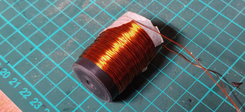
To create the coil I have a reel of magnet wire which is copper wire with a thin enamel coating to prevent short circuits. The reel says 125 gram of 0.4mm diameter wire, no mention of wire length.
WIRE LENGTH
Known figures:


Total volume of copper wire:
Length of copper wire using its volume and radius:
I’ll round down the length of the copper wire to 100m to account for any error in the weight measurement given and to allow for holding on to the wire at each end.
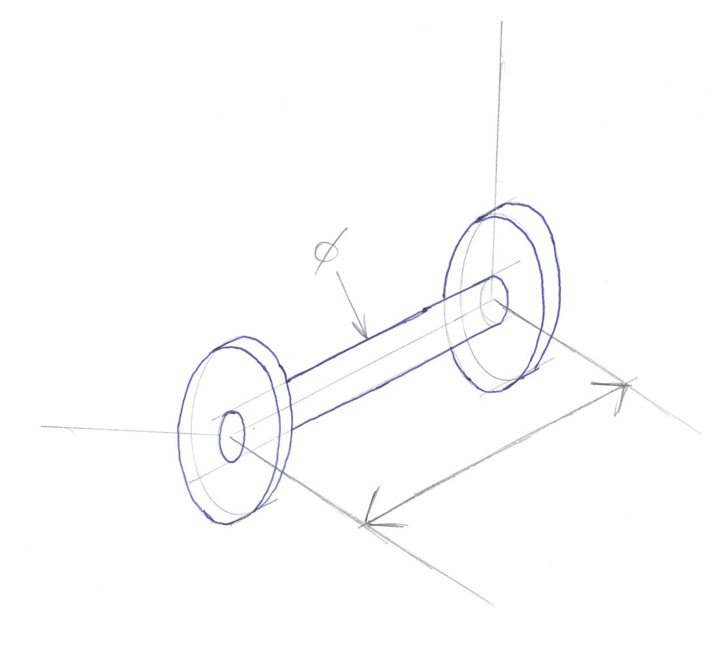
SOLENOID SIZE
The size of the engine is redistricted by my lathe size (65mm max diameter) and tooling size. Starting with the following figures should give a reasonable sized solenoid:
- 30mm between flanges
- 10mm inner drum diameter
- 100m of 0.4mm diameter copper wire
I need to calculate the number of possible coils of wire to find the required flange height. This is done by calculating the amount of wire per turn based on the current drum diameter.


Coils per layer of solenoid:
| Layer | Drum Diameter | Drum Diameter, metre | Circumference, metre | Wire length this layer, metre | Total wire length, metre |
| 1 |  | 0.010 | 0.0314 | 2.355 | 2.355 |
| 2 |  | 0.0108 | 0.0339 | 2.543 | 4.898 |
| 3 |  | 0.011 | 0.0345 | 2.588 | 7.486 |
| … | … | … | … | … | … |
| 23 |  | 0.026 | 0.081 | 6.038 | 97.611 |
Given the maximum amount of layers is 23, the flange height would be:
Adding a little extra to account for error, the final figures for the solenoid are:
- Distance between flanges: 30mm
- Flange Diameter: 30mm
- Inner diameter: 10mm
COIL FABRICATION
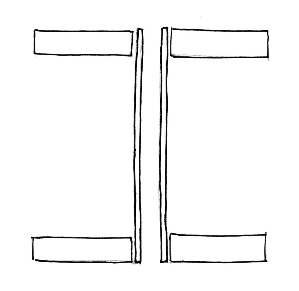
I could have made the part from a solid piece of material, cutting away at the inner section, however I decided to manufacture the inner tube and outer flanges separately and superglue them together to reduce the wasted material involved in turning down the inner diameter. I chose plastic for the inner tube due to its lower friction and ease of machining, this would allow the piston to slide freely within the solenoid. The outer flanges also made from plastic (Nylon), this was a purely aesthetic choice as I liked the contrast to the copper.
After coiling the magnet wire on the holder, I found a problem with the amount of copper on the solenoid. Even after the calculations for flange size there seemed to be too much wire on the part, causing it to extent beyond the flange diameter.
My speculation is that the calculations for each layer of copper on the solenoid assumed a perfect helix of wire, with each layer perfectly arranged on top of each other. But in real life its difficult to get this right, resulting in overlapping in some areas. This overlapping effectively increases the diameter for the next layer, causing a knock-on effect. This can be solved by adding a error percentage to the flange diameter accounting for this effect.
SWITCHING ELECTRONICS
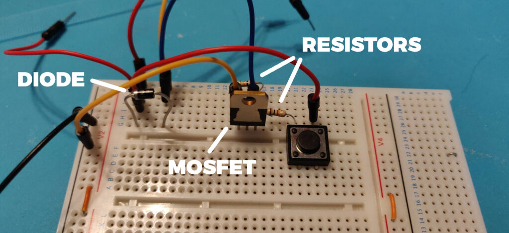
To drive the coil at the correct moment in the engine cycle I’ll use a rocker switch, actuated by a eccentric cam on the shaft. However most switches cannot drive a high current device such as the coil. Therefore I’ll use a MOSFET driving circuit from: https://www.electronicdesign.com/industrial-automation/article/21806574/whats-the-best-way-to-drive-a-solenoid
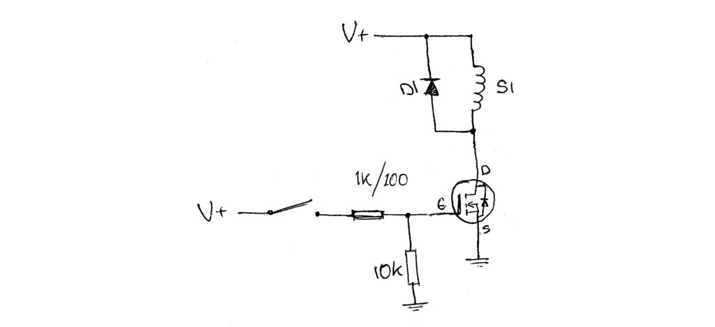
To test if the circuit would work and test the components selected where correct I rigged it up using jumper wire on a breadboard, replacing the lever switch with a board mounted tact switch. After a quick check with a multimeter to find any shorts I applied power using a mains transformer designed for device charging.
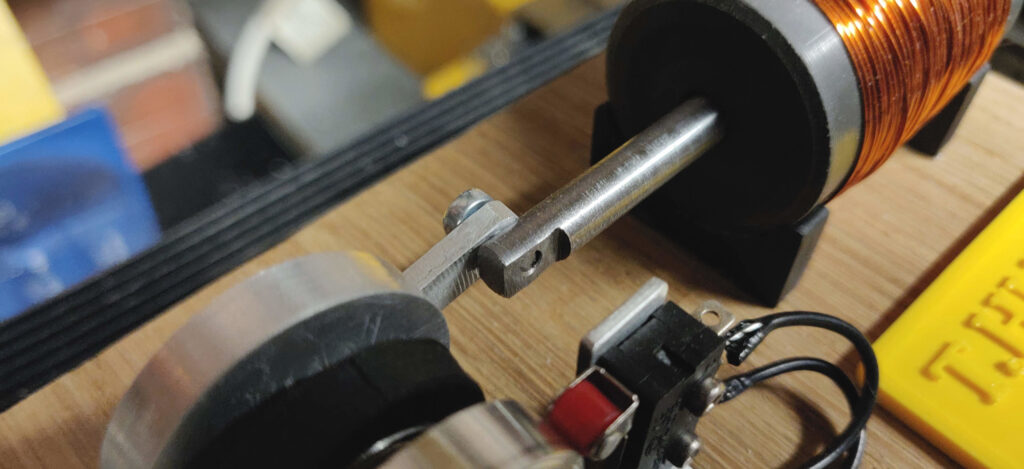
After that quick test I attached the coil to the circuit. No smoke, No excess heat, No sparks, all signs that it works. The proof however was when I partially inserted a steel rod inside the coil:
Applying a voltage of 6v gets a steel piston to move, applying a higher voltage of around 9v moves the piston quicker and with a stronger force.
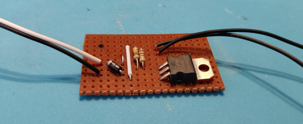
Breadboards are fine for testing a circuit but for a more permanent solution I’ll solder the parts to some copper prototype board, making everything more durable and compact.
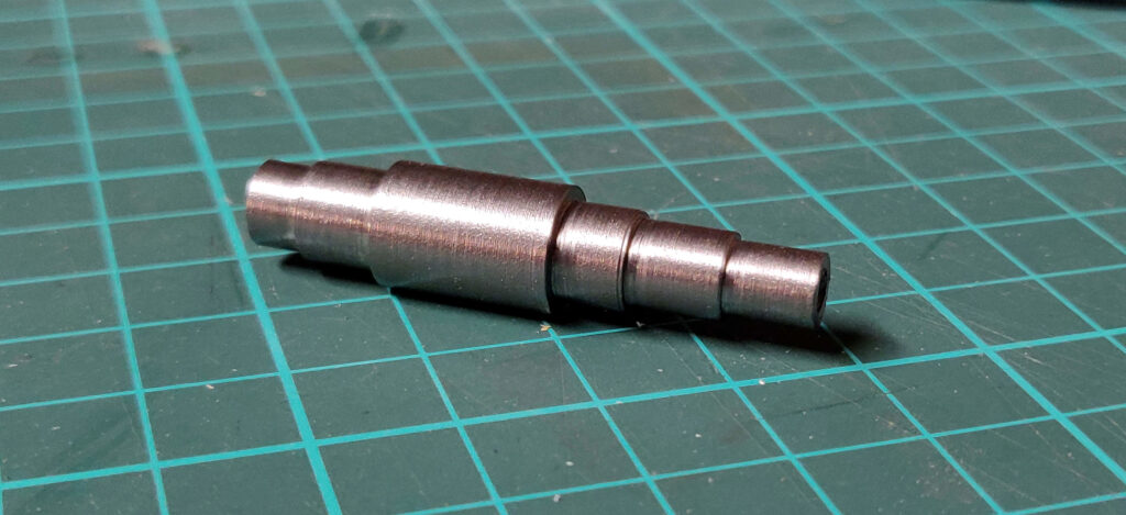
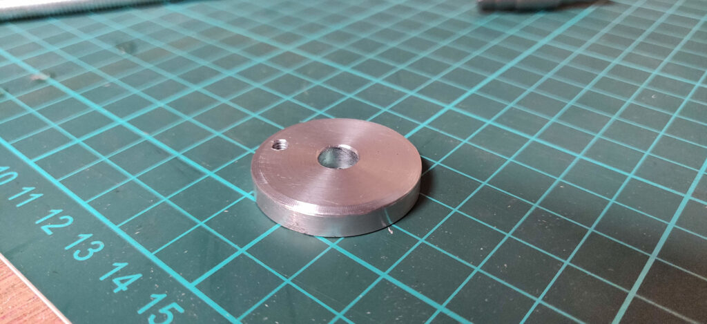
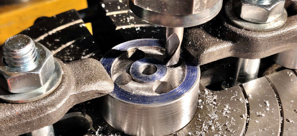
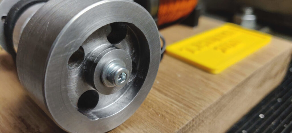
SHAFT, CRANKSHAFT & FLYWHEEL
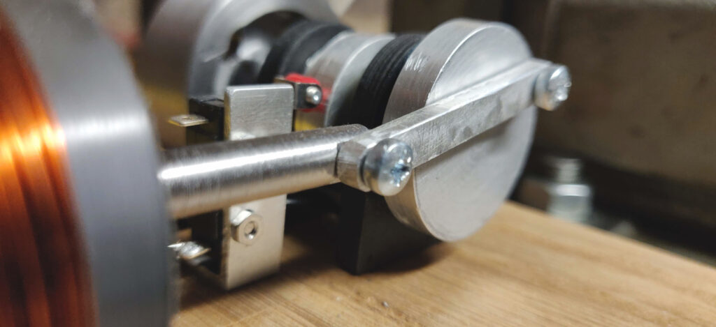
ASSEMBLY
With all the components made it was time to assemble. I designed it all to screw together to allow me to replace parts if needed. I also made a wooden base to present the engine nicely.
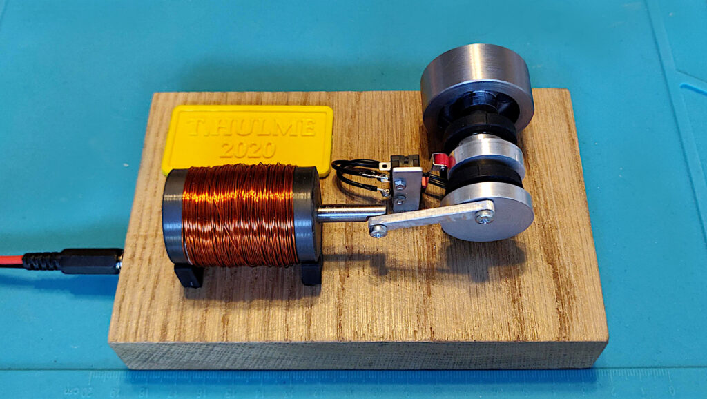
The engines runs!
There are a few improvements to make though:
- Better alignment of the two bearings. There seems to be some extra friction on the spinning shaft, I think down to the two bearings not being concentric. Creating the holder from one piece rather than two should help.
- Use a higher magnetic material for the piston. Having a material with a higher magnetic permeability should improve the strength of the solenoid.
- Larger flywheel. The wheel is a little small for this small engine, making the diameter larger and spokes thinner will improve its ability to smooth the power output.
- Change the rocker switch. Switches have a limited lifespan and switching it on/off this many times will degrade it. Changing to a non contact method such as a hall effect sensor or optical sensor will solve this, allowing the engine to run indefinitely.
- Use the CNC more. It would be great to have more intricate shapes on the engine such as faux weight saving features and text. Using the CNC to make these shapes could be achieved, even parts in brass.